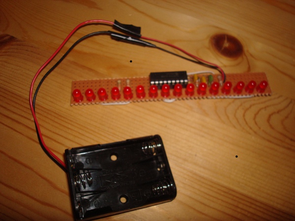
title 'Eye, Copyright by Jose Da Silva, 2009mar20'
list P=16C54
; list P=16F84
list f=INHX8M,C=120,T=on,ST=off
;******************************************************************************
;DIP 16C54 or 16F84 ____ ____
; <-|a2 \/ a1|->
; <-|a3 a0|->
; gnd-Rx120k ->|TOCKI osc1|<-RC=(12k+100pf)=650khz
;3k9+104!MCLR/Vpp->|!MCLR osc2|-> /4
; gnd ->|Vss Vdd|<- +5v
; LEDrow0+ <-|b0 b7|--W--> LEDcol0- <->ICSPDAT
; LEDrow1+ <-|b1 b6|--W--> LEDcol1- <->ICSPCLK
; LEDrow2+ <-|b2 b5|--W--> LEDcol2-
; LEDrow3+ <-|b3 b4|--W--> LEDcol3-
; ----------
;
radix dec
nolist
#ifdef __16C54
#include "P16C5X.INC"
StartR equ 8 ;Start of available RAM
#endif
#ifdef __16F84
#include "P16F84.INC"
errorlevel -224 ;Suppress tris/option warnings
StartR equ 0x0c ;Start of available RAM
#endif
list
__fuses _CP_OFF&_WDT_OFF&_RC_OSC
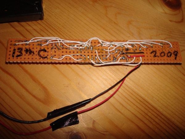
__idlocs h'0904' ;date code - finished 2009, mar20th
;as seen on 13th Colony Battlestar Galactica group on www.meetup.com
#define LEDPORT PORTB
#define BUTTON PORTA,4
#define freq 655000
#define LEDs 17 ;16 LEDs (+1 for looping back)
;******************************************************************************
;RMB substitution from V5 to V8 code migration (TY RES solution, jun2011)
rmb macro bytes
org $
org $+bytes ;...next loc
endm
;******************************************************************************
org StartR
nxtLEDt rmb 1 ;next primary LED to light from 3 LED table
LEDprtV rmb 4 ;port values for 3+1 LEDs
temp rmb 2 ;temporary storage used by subroutines
countB rmb 2 ;large loop of about 1000x4x17x2
dataOut rmb 2 ;data to transmit out
Atris rmb 1 ;Current state of output PORTs
Aport rmb 1
org 0
#ifdef __16F84
goto Reset
goto Reset
goto Reset
goto Reset
goto Reset
#endif
;******************************************************************************
;4 LED Table, this table lists 4 LEDs in sequence from the 16 LED 4x4 matrix.
;enter: w=LED.table.position
;exit: w=matrix.tris.value required to light this LED
;time: 4cycles
LED4tbl addwf PCL,f ;get Table Value based on entry with W register
Delay4 retlw 0 ;delay 4 cycles {call=2, retlw=2}, note: Wreg=0
dt b'11100111',b'11010111',b'10110111',b'01110111'
dt b'11101011',b'11011011',b'10111011',b'01111011'
dt b'11101101',b'11011101',b'10111101',b'01111101'
dt b'11101110',b'11011110',b'10111110'
dt b'01111110',0xff,b'01111110'
dt b'10111110',b'11011110',b'11101110'
dt b'01111101',b'10111101',b'11011101',b'11101101'
dt b'01111011',b'10111011',b'11011011',b'11101011'
dt b'01110111',b'10110111',b'11010111',b'11100111',0xff
LED4end equ $
dt 0xff,0xff
;******************************************************************************
Delay22 goto $+1 ;2,total delay is 22 cycles (include call/retn)
goto $+1 ;2
goto $+1 ;2
goto $+1 ;2
goto $+1 ;2
Delay10 goto $+1 ;2
goto $+1 ;2
Delay6 goto Delay4 ;delay 6 cycles {call,goto,retlw}, note: Wreg=0
;******************************************************************************
;{10,4,2}cycles x (loops for 2 seconds)
;{
;LED routine to use less program space while repeatedly showing LEDs total 75x
;enter: LEDprtV[0..2]=port values for LED output,countr
;exit: w=0
;calls: Delay4,Delay6,Delay10
;time: 4096cycles+2154cycles=6250cycles
;values located in LEDprtV[0,1,2]
;do this for 2/3. Loop for 1/34*2=2seconds={10,4,2}=freq/4/16/256*2/17/2 * 2/3
LEDrtn movlw freq/24576/LEDs+1 ;1,1/34 and 2/3rd of 2 seconds
movwf temp ;1,time=2seconds
movlw (freq/96/LEDs & 0xff)+1 ;1,1/34 of 2 seconds
movwf temp+1 ;1,
LEDrtn1 btfss BUTTON ;1,"fancy" or "simple" LED display
goto LEDrtn2 ;2,go do "fancy" LED version
goto $+1 ;2,delay, "simple" 1 LED version
goto LEDrtn3 ;2,done
LEDrtn2 movfw LEDprtV+2 ;1,output LEDPORT=LEDprtV[2]
tris LEDPORT ;1,
movfw LEDprtV+1 ;1,output LEDPORT=LEDprtV[1]
tris LEDPORT ;1,
LEDrtn3 movfw LEDprtV+0 ;1,output LEDPORT=LEDprtV[0] (brightest)
goto $+1 ;2,delay
tris LEDPORT ;1,
goto $+1 ;2,delay
decfsz temp+1,f ;1,looped 256 times?
goto LEDrtn1 ;2,not yet, do more
decfsz temp,f ;1,looked long enough?
goto LEDrtn1 ;2,not yet, do more
;----------------------------------------------------------------------
;move next LED pointer to next LED to display
movfw LEDprtV+2 ;1,output LEDPORT=LEDprtV[2]
tris LEDPORT ;1,
movfw LEDprtV+1 ;1,output LEDPORT=LEDprtV[1]
tris LEDPORT ;1,
movfw LEDprtV+0 ;1,output LEDPORT=LEDprtV[0]
goto $+1 ;2,
tris LEDPORT ;1,
decfsz nxtLEDt,w ;1,point to next LED to glow
goto LEDrtn4 ;2,do the opposite of decsz
movlw LEDs*2 ;1,if reached end, loop to beginning
LEDrtn4 movwf nxtLEDt ;1,update pointer to next LED in table
movfw LEDprtV+2 ;1,move LEDs down array
movwf LEDprtV+3 ;1
movfw LEDprtV+1 ;1
movwf LEDprtV+2 ;1
movfw LEDprtV+0 ;1
movwf LEDprtV+1 ;1
;----------------------------------------------------------------------
;get next LEDprtV[0] value to display
movfw LEDprtV+3 ;1,output LEDPORT=LEDprtV[2]
tris LEDPORT ;1,
movfw LEDprtV+2 ;1,output LEDPORT=LEDprtV[1]
tris LEDPORT ;1,
movlw freq/49152/LEDs+1 ;1,1/34 and 1/3rd of 2 seconds
movwf temp ;1,time=2seconds
movfw LEDprtV+1 ;1,output LEDPORT=LEDprtV[0]
tris LEDPORT ;1,
movlw (freq/192/LEDs & 0xff)+1 ;1,1/34 of 2 seconds
movwf temp+1 ;1,
movfw nxtLEDt ;1,prepare to collect next new location
call LED4tbl ;6,go get next table location
movwf LEDprtV+0 ;1,hold new value in LEDprtV[0]
;----------------------------------------------------------------------
;display 4 LEDs since we are moving to next LED {5,6,3,2}
LEDrtn5 movfw LEDprtV+3 ;1,output LEDPORT=LEDprtV[2old]
tris LEDPORT ;1,
movfw LEDprtV+2 ;1,output LEDPORT=LEDprtV[1old]
tris LEDPORT ;1,
movfw LEDprtV+1 ;1,output LEDPORT=LEDprtV[0old]
nop ;1,
tris LEDPORT ;1,
goto $+1 ;2,
goto $+1 ;2,
movfw LEDprtV+0 ;1,output LEDPORT=LEDprtV[0new]
tris LEDPORT ;1,
decfsz temp+1,f ;1,looped enough?
goto LEDrtn5 ;2,not yet, do more
decfsz temp,f ;1,
goto LEDrtn5 ;2,not yet, do more
;----------------------------------------------------------------------
;done, exit routine while displaying LEDs
movfw LEDprtV+2 ;1,output LEDPORT=LEDprtV[2]
tris LEDPORT ;1,
movfw LEDprtV+1 ;1,output LEDPORT=LEDprtV[1]
tris LEDPORT ;1,
movfw LEDprtV+0 ;1,output LEDPORT=LEDprtV[0]
goto $+1 ;2,
tris LEDPORT ;1,
goto Delay10 ;10,done
;******************************************************************************
;look in a given direction for 2 seconds {2,13,2}cycles = freq/4/17/256*2
LEDlk movlw freq/512/LEDs+1 ;1,look in directionX for 2 seconds
movwf temp ;1,time=2seconds
clrf temp+1 ;1,
LEDlk1 btfss BUTTON ;1,"fancy" or "simple" LED display
goto LEDlk3 ;2,go do "fancy" LED version
goto $+1 ;2,do "simple" 1 LED version
goto LEDlk4 ;2,go reload 1 LED
LEDlk3 movfw LEDprtV+0 ;1,output LEDPORT=LEDprtV[0]
tris LEDPORT ;1,
movfw LEDprtV+2 ;1,output LEDPORT=LEDprtV[2]
tris LEDPORT ;1,
LEDlk4 movfw LEDprtV+1 ;1,output LEDPORT=LEDprtV[1] (brightest)
tris LEDPORT ;1,
call Delay4 ;4,delay
nop ;1,delay
decfsz temp+1,f ;1,looped 256 times?
goto LEDlk1 ;2,not yet, do more
decfsz temp,f ;1,looked long enough?
goto LEDlk1 ;2,not yet, do more
retlw 0 ;done, continue
;******************************************************************************
Reset movlw b'00001111' ;set options register
option
movlw 0 ;Start with all ports as outputs low
movwf PORTA
;reset needed for 18 pin 16c54 type chip
movwf Aport
movlw b'00010000' ;{a3..a0}=N/A, a4=BUTTON=input_N/A
tris PORTA
movwf Atris
movlw b'11111111' ;{b7..b0}=set all LEDs start as off
tris PORTB
movlw b'00001111' ;direction 4pins=+0V ---> 4pins=+5V
movwf PORTB
;----------------------------------------------------------------------
movlw LEDs/2 ;init to point at middle LED to begin glowing
movwf nxtLEDt
call LED4tbl ;init LEDprtV[0,1,2] before calling routine
movwf LEDprtV+0
movlw LEDs/2+1
call LED4tbl
movwf LEDprtV+1
movlw LEDs/2+2
call LED4tbl
movwf LEDprtV+2
;----------------------------------------------------------------------
movlw (50*LEDs*2/256)+1 ;loop 100 cycles for the 1st time
movwf countB ;approx 2x100 seconds or 1.4 minutes
movlw ((50*LEDs*2) & 0xff)+1
movwf countB+1
goto main1
;------------------------------------------------------------------------------
;main loop does everything here as a 'state machine' to keep correct timing
main movlw (1000*LEDs*2/256)+1 ;loop 1000 cycles
movwf countB
movlw ((1000*LEDs*2) & 0xff)+1
movwf countB+1
;----------------------------------------------------------------------
main1 call LEDrtn ;24,glow 3 LEDs
;----------------------------------------------------------------------
;need to loop while also maintaining synchronized glow pattern
decfsz countB+1,f ;done yet?
goto main1 ;not yet
decfsz countB,f
goto main1 ;not yet
call LEDlk ;look in directionX for 2 seconds
goto main ;reset and do it again
;******************************************************************************
dt "Copyright Jose Da Silva 2009mar20 Vancouver BC"
;******************************************************************************
#ifdef __16C54
org 1FFh
goto Reset ;program starts here on reset
#endif
end |